|
|
|

|
| |||||||||||||||||||||||||
|
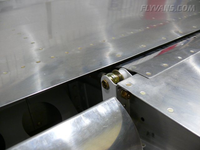
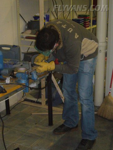
Finally, another update! Although this winter has been pretty bad what building is concerned so far, we haven't been standing still. There's just lots of things going on right now and there is more change coming in the future, stay tuned... As usual on the fuselage, we have several construction sites active at any one time... For the aileron control stops Dominik prepared some delrin stock we got from Mickey who also brought up the idea. Thank you very much, guys. 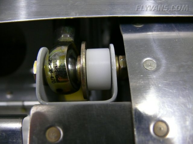
And in a greater overview. The delrin will hit the aileron attach bracket thereby limiting control-uptravel within specs.
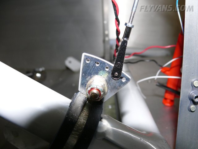
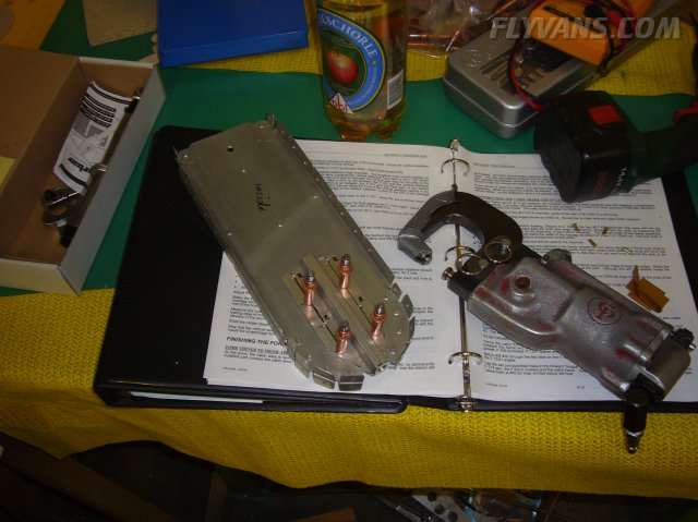
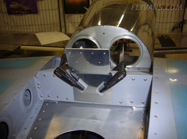
Also, we had to design an electrical flap position indicator. Apparently (we have yet to have someone show us the regs requiring it really, but that's a completely different story...) from hearsay, the local regs require a position indicator for any flap system that isn't manually actuated/the position can be felt... So what the heck, instead of going down the papertrail we decided to just build one, after all there's some utility to it.
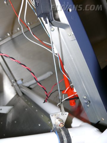
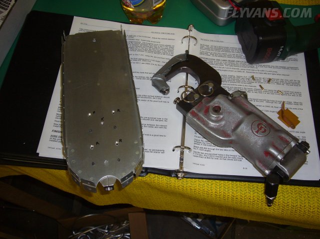
It's basically made up of an RC-Allen position sensor attached to an angled bracket on the vertical flap channel, a scale model type pushrod and an adel clamp on the flap weldment. By adjusting length and mounting position the optimal travel range for the sensor is obtained.
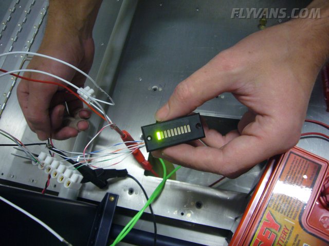
One of these indicators will be mounted in the panel, indicating flap position.
The QB came with the rear bulkhead only temporarily mounted...
Such that the tiedown ring holder can be installed and the pilot holes for the VS attach bolts drilled.
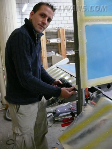
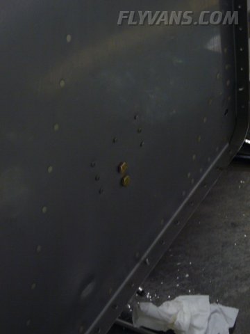
Riveting the bulkhead to the fuselage.
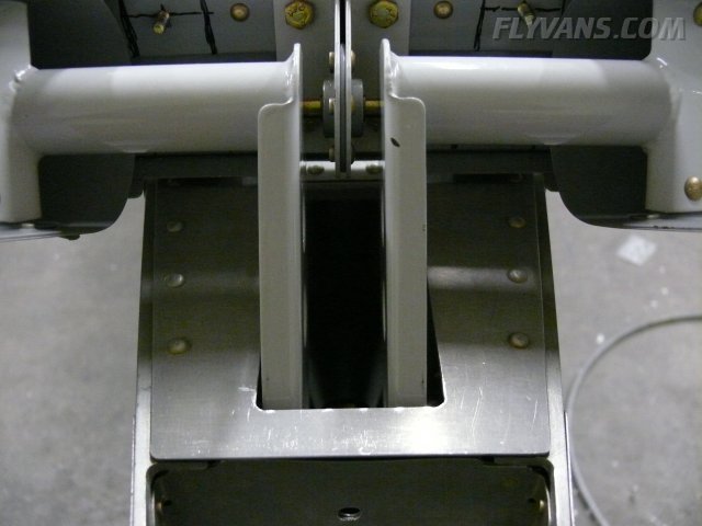
In order for the elevators to be rigged and control stops to be installed, temporary bolts are put in place.
Unlike many other builders, we have very little difference between left and right weldment to report. Only that the left one is a bit shorter than the right one, giving less clearance to the cutout in the topdeck.
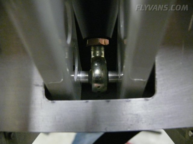
Now the main pushrod connecting the elevators with the belcrank can be installed and its length adjusted.
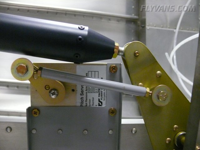
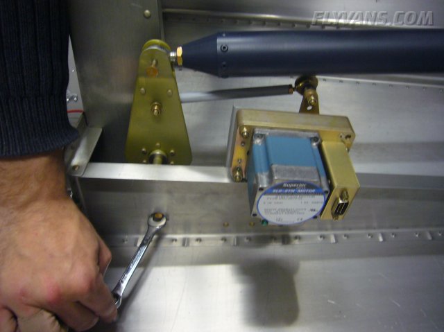
The other end in place. Also, the autopilot pitch servo plus connecting hardware installed.
This technique is even recommended by the plans to determine belcrank "neutral" position.
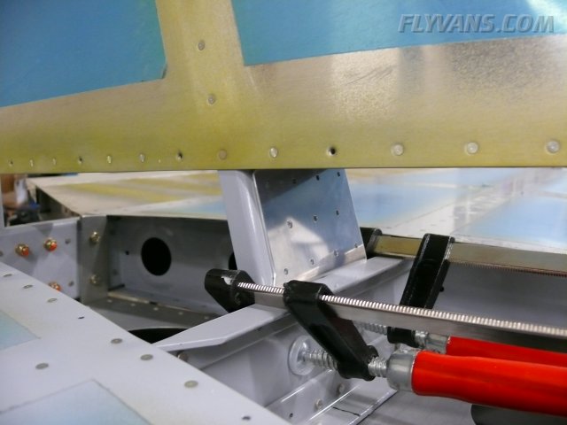
Another result of the almost even weldments is that the regular up-controlstop (a specially shaped piece of angle) allows too much travel. Therefore a spacer, exactly .125", the thickness of an angle side had to be made.
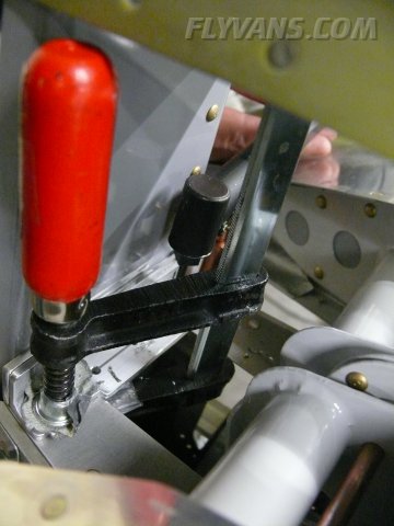
The control stop angle can only be drilled to the fuselage while the VS is temporarily clamped in position.
The VS forward spar had to be trimmed according to plans, so that it fits straight onto the fuselage mount..
With the rear VS spar in position, the control stop bracket with the spacer can be drilled to the longerons.
Very tricky to drill without damage to the elevators.
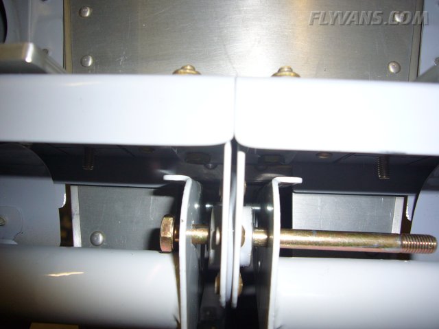
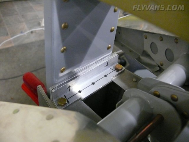
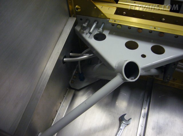
The control stop in place, this time limiting up-travel just within specs. Note the spacer between the VS spar and the main bracket. The 2 horizontal pilot holes will be used to drill the boltholes to the vertical stabilizer. This hasn't been done yet. The stab has to be more precisely adjusted and its position confirmed, first.
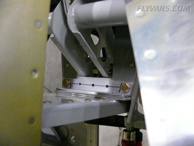
Same area from a different point of view.
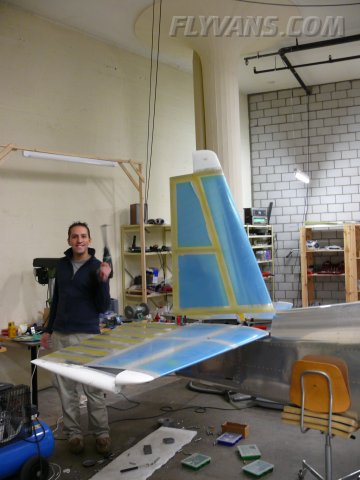
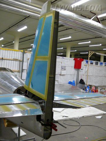
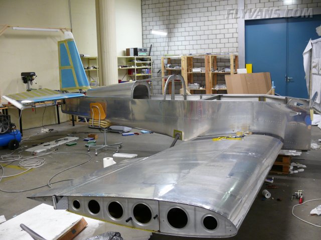
Ever more looking like a completed airplane :-)
The front spar waiting to be mounted.
And as the last piece in the puzzle, the rudder will go on once the VS is attached.
Next major milestone: Having the canopy on by the end of 2007...
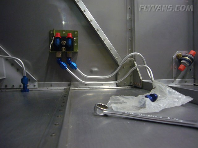
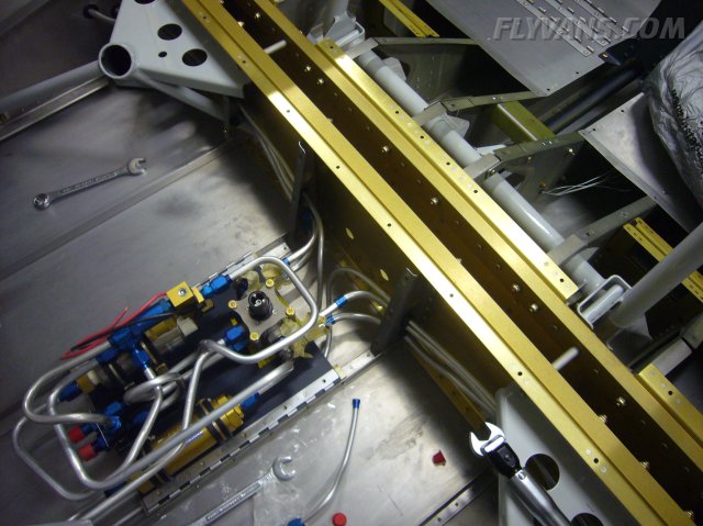
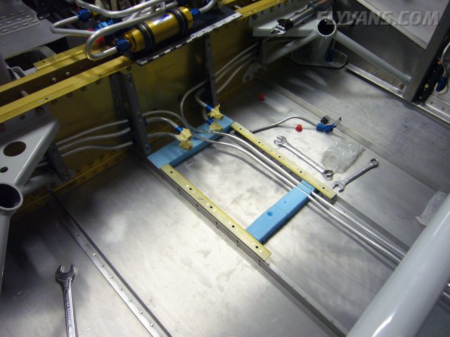
Also, we finally received the correct AN-Fittings from Spruce to allow for a nice installation of the parking brake valve and corresponding lines.
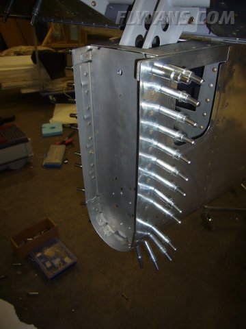
The brake lines pass under the fuel pump assembly and then use the same brackets as the fuel lines leading outwards.
3 lines in these close quarters plus wing attach bolts... I guess this will make for an interesting final installation once at the hangar ;-) Note the brake line exiting in the vertical. They lead straight into an angled AN-Fitting which will connect to a line running parallel to the main gear leg.
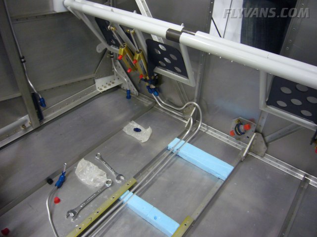
The original firewall position where the flexible brake lines transfer to the aluminum tubing have been used for our parking brake valve mount. The bracket itself is riveted to the firewall while the valve is attached with 2 bolts.
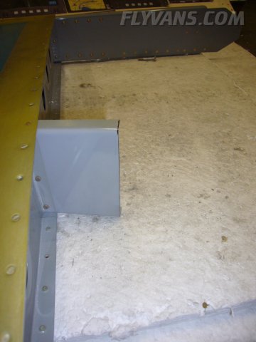
The brake lines are supported by some blocks made of styrofoam. This should prevent rattling and chafing.
Bending/routing all those lines was a major PITA...
|
|
|||||||||||||||||||||||||
|
||||||||||||||||||||||||||
|