|
|
|

|
| |||||||||||||||||||||||||
|
We have been VERY busy building, hence the website suffered from lack of attention ;-) This doesn't mean we're not making progress! In fact we're getting ever closer to painting and moving to the airport... Certainly will happen this year!
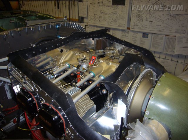
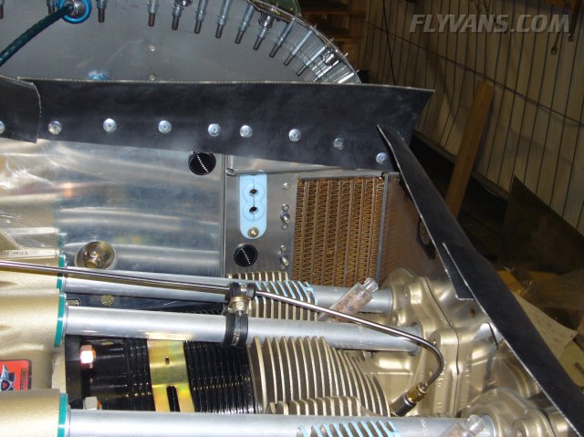
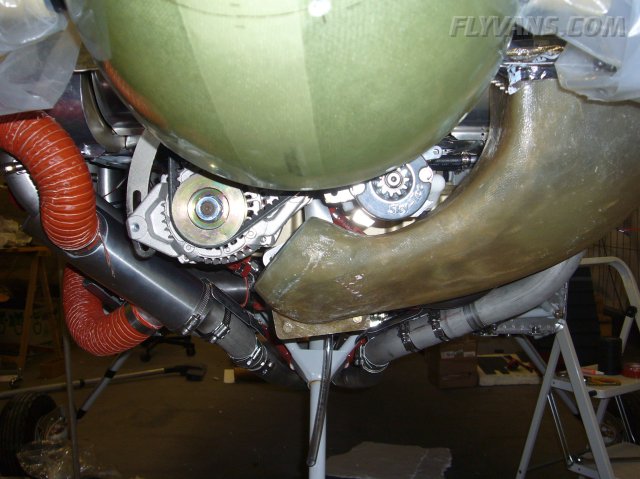
Baffling is complete, only lacking the finishing touches with high temp red silicone, which we'll do in one session when the wiring pass through at the firewall is at the same stage.
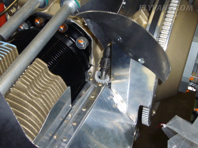
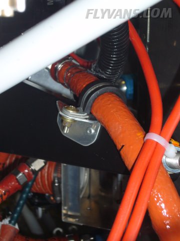
A "proper" grommet would have weakened the baffling at this critical location because of the required oversize hole. So we protected the prop line with this heavy duty caterpillar strip, plus it will be sealed with high temp silicone as well.
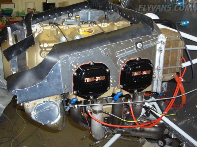
Blast tubes and ignition wire pass-through installed as well.
Same things on the left side.
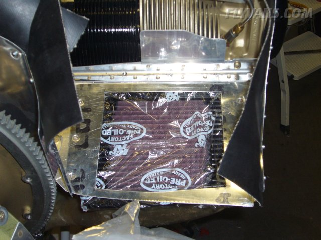
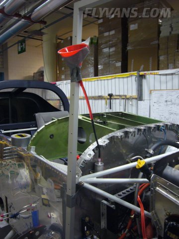
The air filter is waiting to be unwrapped before first engine start. For now it protects the air inlet very well this way.
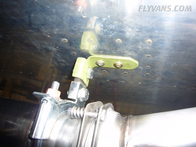
Note the small black rubber part with the bolt on the rear on each side baffling. These are access holes for the spark plug wrench on the rear cylinders. Also the alternate air kit is installed in place. (Flap on the left side of the airbox)
A more detailed view. In case the filter gets clogged for some reason (most often because of icing in IMC conditions, highly improbable during our VFR operation) this provides an alternate path for air to enter the engine and keep it running, at least with lower power.
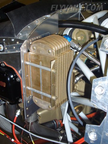
Oil cooler.
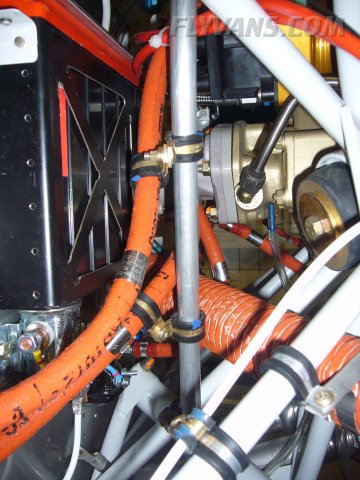
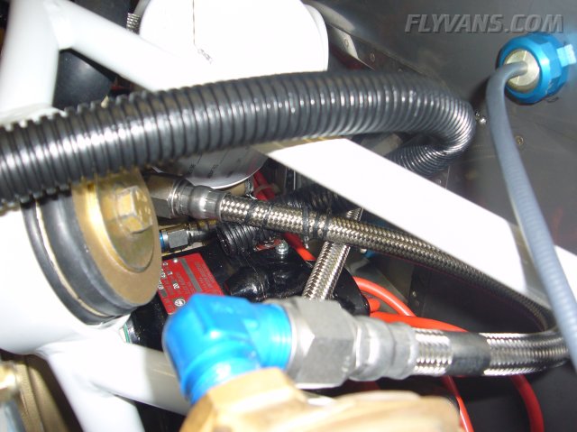
Fabbed some small brackets such as this one to avoid chafing of fuel lines etc...
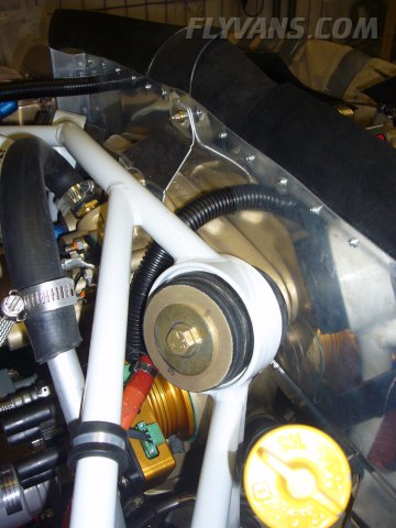
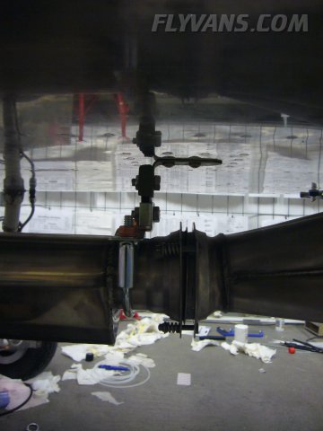
Heat shields in the area of the control cables.
Same area seen from the front.
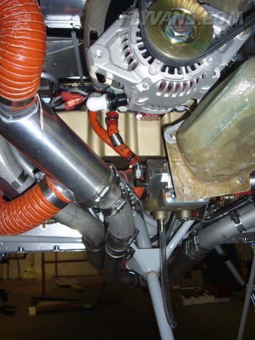
The final clearance between the alternator, starter and airbox. There is a bit room for the alternator belt to expand. Otherwise, we'd have to get a shorter belt... Hope the default one will do however, as exchanging involves removal of the prop!
Only missing items are now the firewall forward wires.
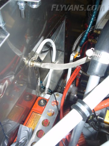
Started doing some of them, here's the alternator main wire (B-Lead).
The alternator wire goes through a 60A ANL fuse and then onto the main bus.
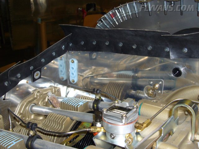
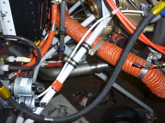
The breather line offers a nice support for various adel clamps.
Blast tubes are very simple, we'll see how they hold up. They provide fresh/cooler air to critical components such as P-Mag, fuel pump and magneto thereby increasing the margin to overheating/heatsoaking.
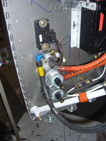
The main firewall ground is a fat AN-4 bolt.
Baffling looks so simple, but was a TON of work! At least more fun than fiberglass...
Blast tube to the magneto.
Started building up and test fitting the instruments / panel.
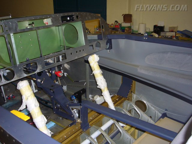
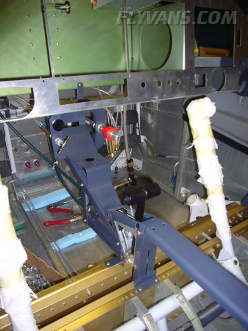
Even though we took great care and tried to measure everything in 3D, some interferences were unavoidable. The most critical one was this area. As the vertical position of the autopilot was given by the radio stack and the autopilot (including eventual fittings, connectors etc...) proved to be deeper than expected, this lead to interference with the canopy support brace.
Otherwise the panel planning only is being adjusted with very minor details. Solution to the canopy interference problem is to move some of the backup switches to the top row and put the autopilot below the radio stack. We have to have a new panel cut though... Thanks to CAD/Laser this isn't such a big setback.
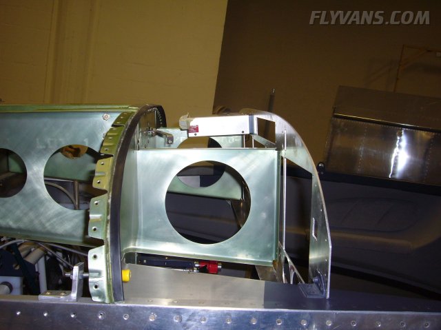
The reinforcement angle for the upper edge of the panel was also fitted.
Needed some mods, as some instruments are in the absolute topmost locations ;-) Efficient use of panel real estate...
We have quite a building spree going as Lex is back in town for good.
Support construction for the radio stack trays. Also planned in 3D CAD by Markus :-)
Also, bled the brake system. However the nylon tee near the reservoir leaked air (even though tight for fluid) so we have short brake lines and fittings on order to replace that before we can finish the brake system.
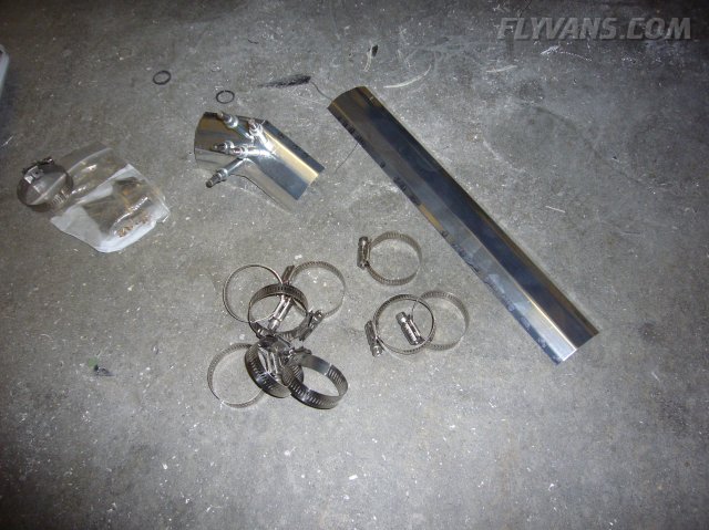
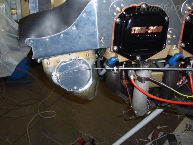
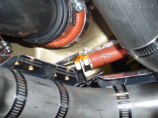
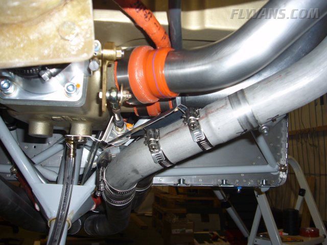
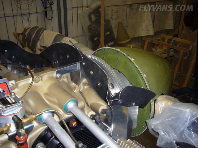
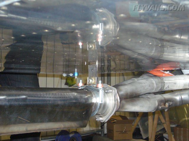
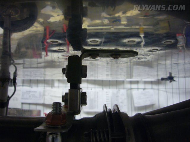
Another long-time open item was additional support for the exhaust construction.
Paid a visit to the neighbouring auto parts store, and with the help of one of their specialists combed through the complete car-exhaust-mount inventory. Came up wit a slick flexible mount. Jury is out on real life performance, aerodynamics and wheter it's too stiff or too lose. This will be one very important area to watch during engine start / testing on ground and during the first few hours. (Besides the usual other important things of course)
The bracket consists of a clamp around the muffler, a fortified piece of rubber bolted to a bracket mounted on the fuse. We redid the upper part of the bracket from aircraft aluminum and primered it to avoid potential problems with dissimilar metals/corrosion.
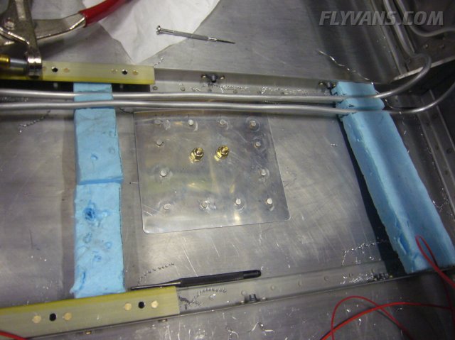
Also, there was a .063" doubler added to the bottom fuse skin of course.
The bracket itself is held by 2 AN3 size aircraft bolts/screws.
|
|
|||||||||||||||||||||||||
|
||||||||||||||||||||||||||
|