|
|
|

|
| |||||||||||||||||||||||||
|
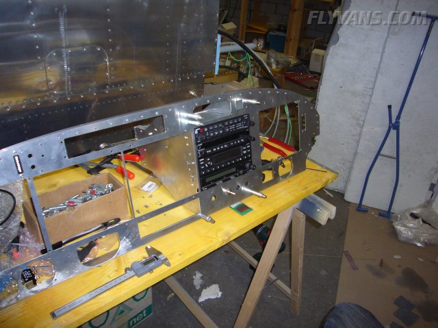
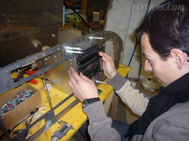
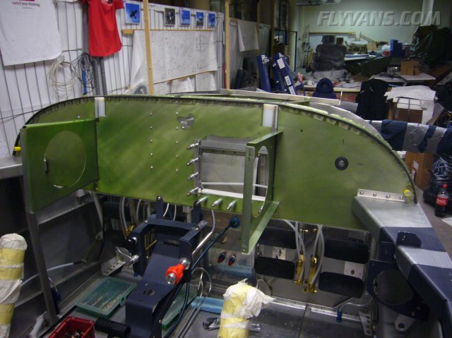
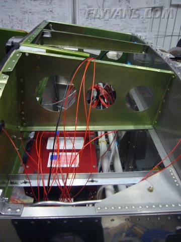
While waiting for the final panel, we continue to build up / prepare the installation of course. Here's the radio stack in place.
One major challenge is the minimum space for nuts and washers at the front of the trays due to neighbouring avionics. However an inch or two back there is plenty of room.
Only the radio stack is deeper than the subpanel, needing a cutout.
We fitted everything so that the right longitudinal rib doesn't need any modification.
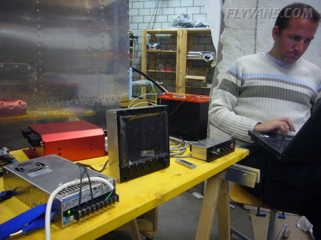
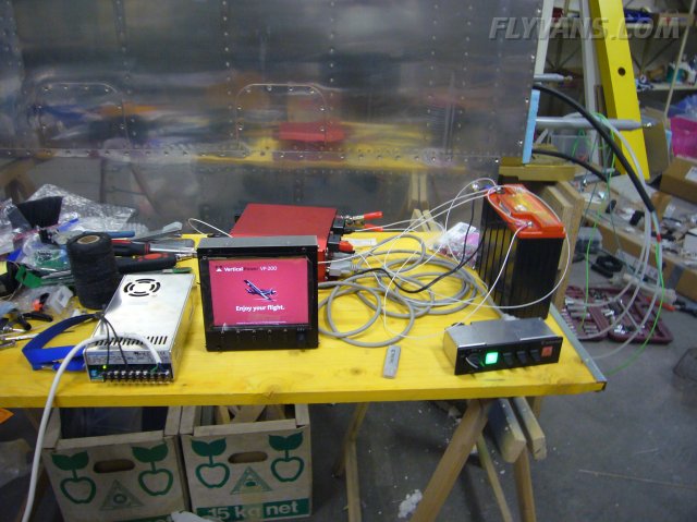
Before installation, we bench-tested the Vertical Power VP-200 and made the latest software upgrades.
Everything worked like a charm and we'll see how installation in the aircraft goes.
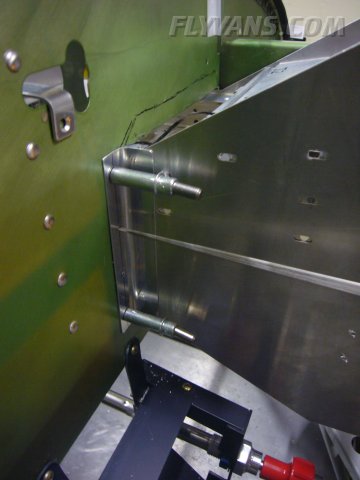
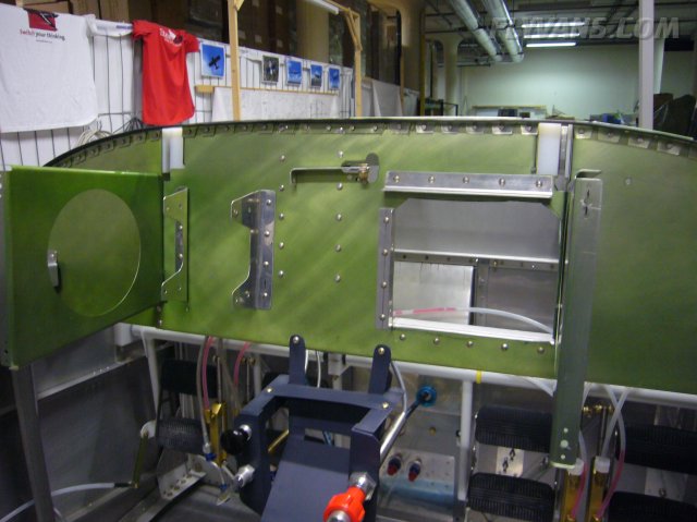
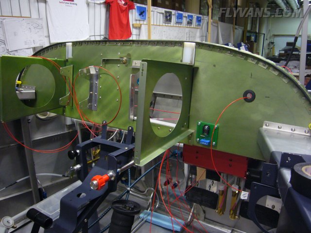
The cutout in the subpanel being reinforced, at the same time supporting the radio stack.
The overlap of the trays on the back.
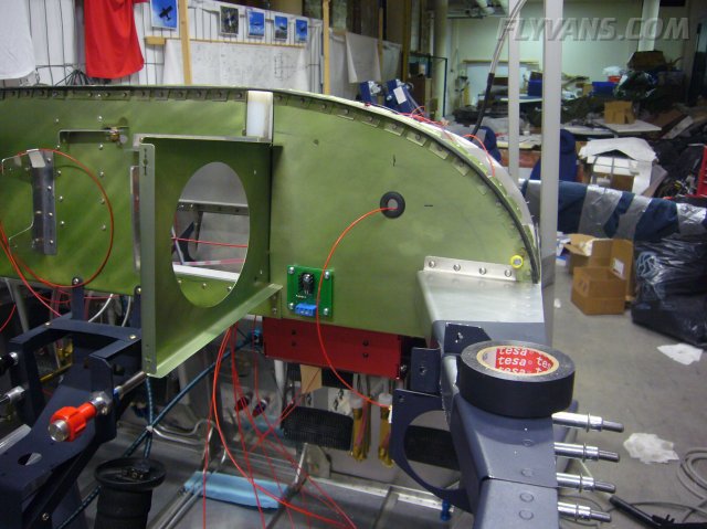
The grommet on the right is for one of the AF3400EM harnesses.
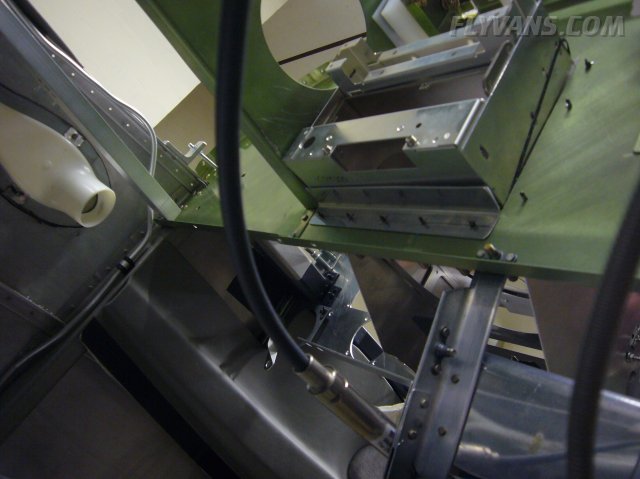
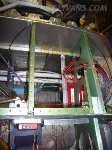
The cutout reinforcements riveted in place. Also, the 2 brackets on the left will hold the ARINC converter box and the AOA CPU box.
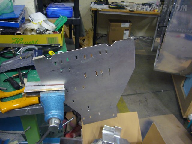
The left longitudinal rib will need a mod as the MapPC Display Unit will be placed right there.
The radio stack support get some treatment and additional holes.
Started pre-fitting the VP200 harnesses. Checking pin assignments and which length of cable goes where.
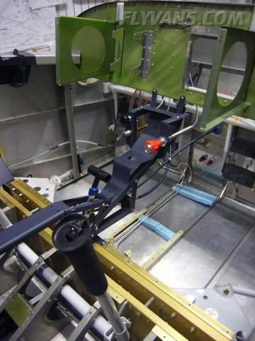
Another small item mounted, the dimmer control from Van's.
The position of the VP200 Control Unit can be clearly seen, hanging upside down above the passenger feet. Clearance is no problem and one would have to kick pretty wildly to reach it.
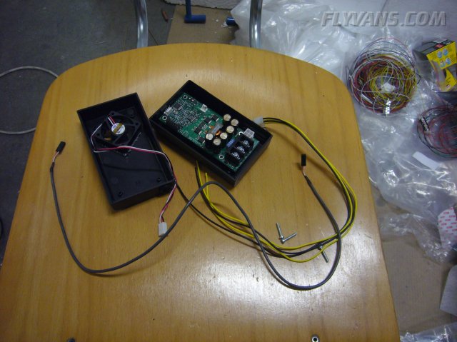
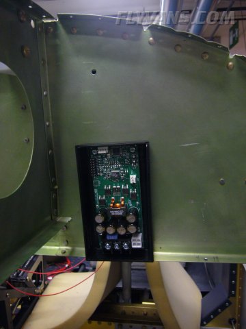
As aircraft electrical systems (and of cars) have variable voltage and the MapPC display driver needs stabilized 12V, we're using this small DC-DC power supply from http://www.mpegbox.com/products.html
Installed on the backside of the subpanel on the pilot side.
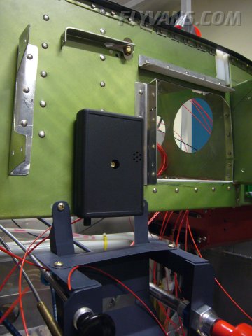
This small unit is the FLARM brainbox. A small and lightweight GPS/Collision Avoidance System. Although it uses a proprietary solution/protocol not relying on transponder and requiring the other station to be fitted with one as well, almost every glider around Central Europe has one of these installed. This should help greatly avoid circling gliders which are hard to see. Usually, this would be mounted directly on a glareshield. We interface it to the MapPC where the warnings are displayed and integrated.
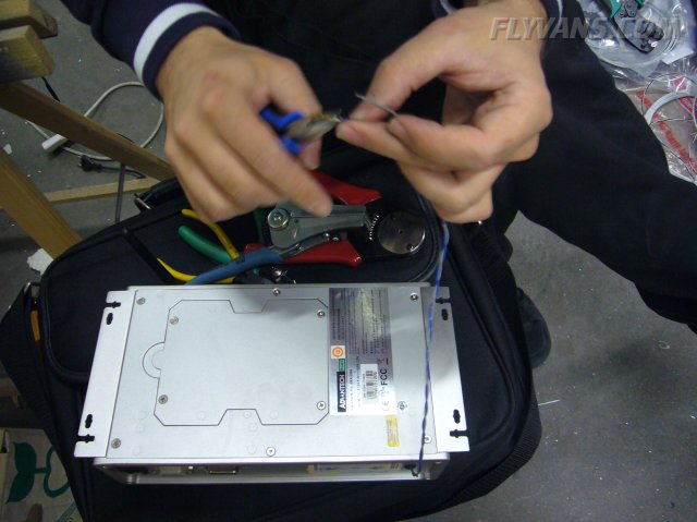
Modding the MapPC CPU for the power button to be remote controlled by the DC-DC power supply, allowing a controlled startup/shutdown.
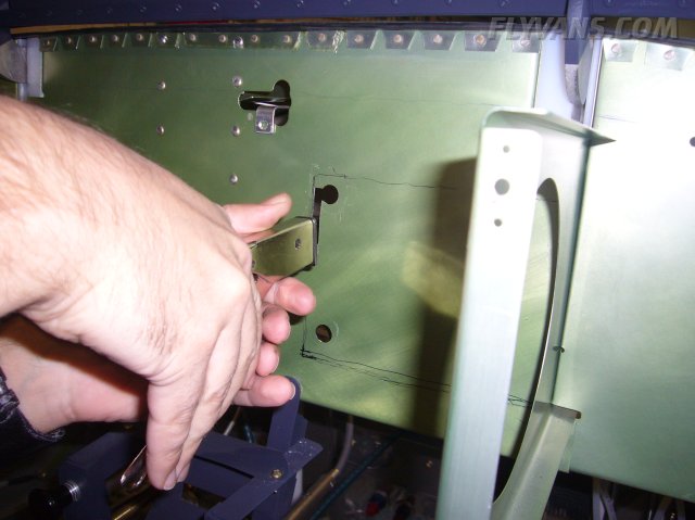
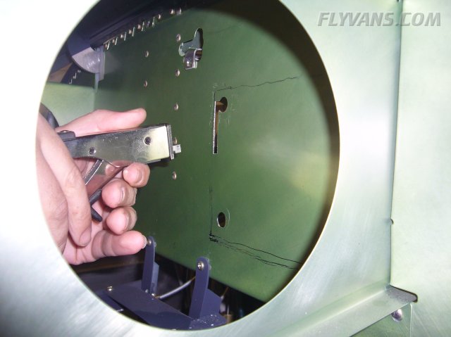
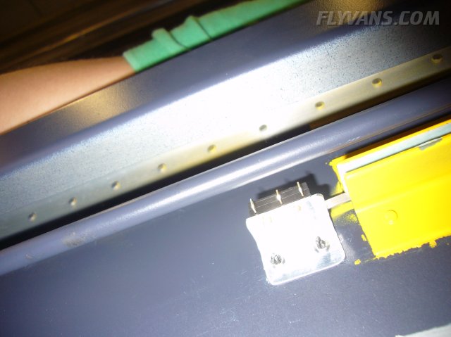
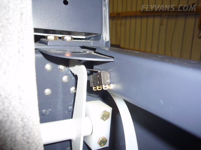
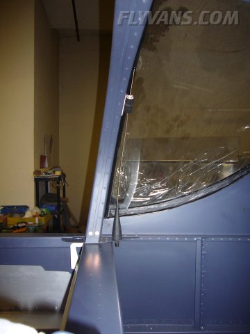
Here's a very simple canopy lock indication using 2 microswitches in series. The first one checks wheter the main latch is in the locked position.
And the second one checks that the canopy is not "riding" on the latch but is actually held down by it.
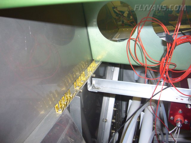
Our main firewall grounding strips from the inside of the cabin.
Getting a bit crowded.
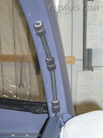
The FLARM communication antenna is a short stub that we velcroed to the inside of the rollover bar.
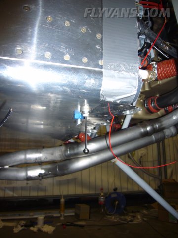
Transponder antenna mounted near the front right fuel tank vent.
A used ELT antenna mounted behind the rollover bar on the right side should work as COM2 (short range/mostly receive) antenna. If this doesn't work out, there's always an option to go external or so.
|
|
|||||||||||||||||||||||||
|
||||||||||||||||||||||||||
|