|
|
|

|
| |||||||||||||||||||||||||
|
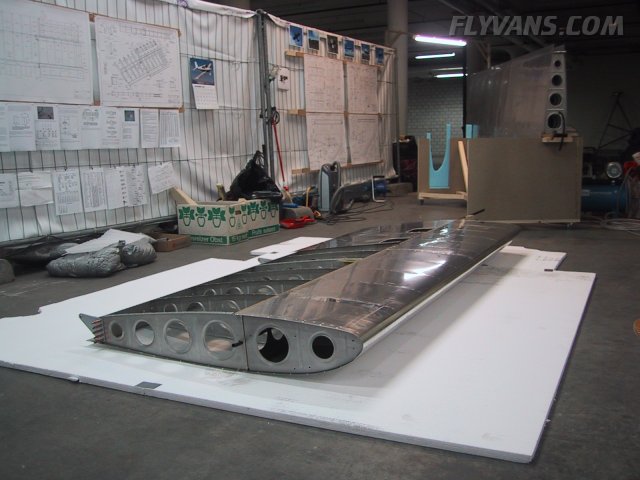
Before we started with the landing light installation, we cleaned out the shop... Interesting how quickly aluminum dust and other trash accumulates... 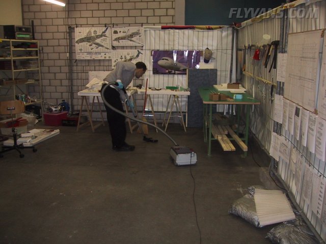
Then we lifted the left wing out of the cart and put it upside down onto the large styrofoam pads that came with the QB wing crate.
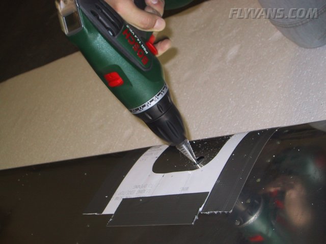
A very "expensive-if-not-done-at-the-right-place" hole *G*
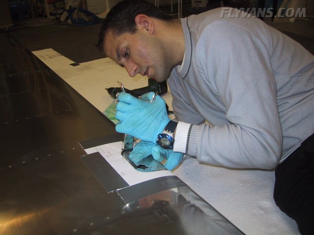
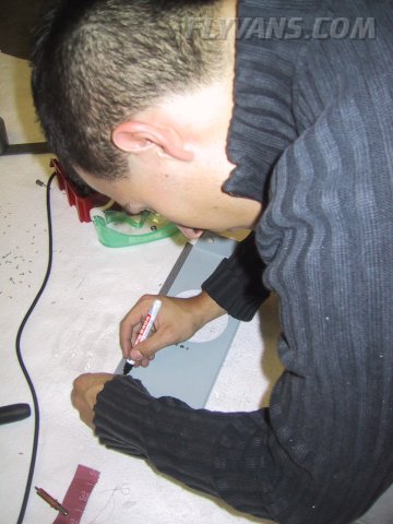
As a starting point for the landing light cutout, you need a hole large enough for tools (nibbler, snips or whatever) to cut. The paper template fits very nicely but we recommend you mark the cutout on the skin first, as the paper can be damaged during work. Therefore it's good to have a reference on the aluminum, too.
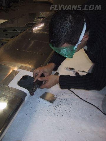
With a little practice, this technique gets you there quite fast even though the nibbler only cuts small bits at a time. It also produces We also tried cutting with a wheel on the dremel but this proved to be more of a hassle, at least for the main cut. Another advantage with the nibbler is that it produces chips which can be easily vacuumed/cleaned up.
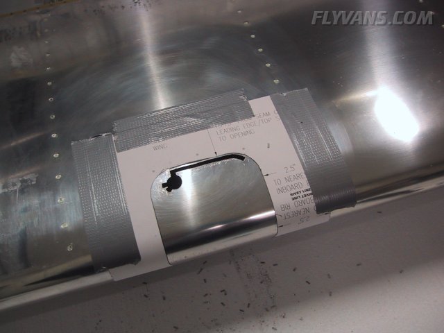
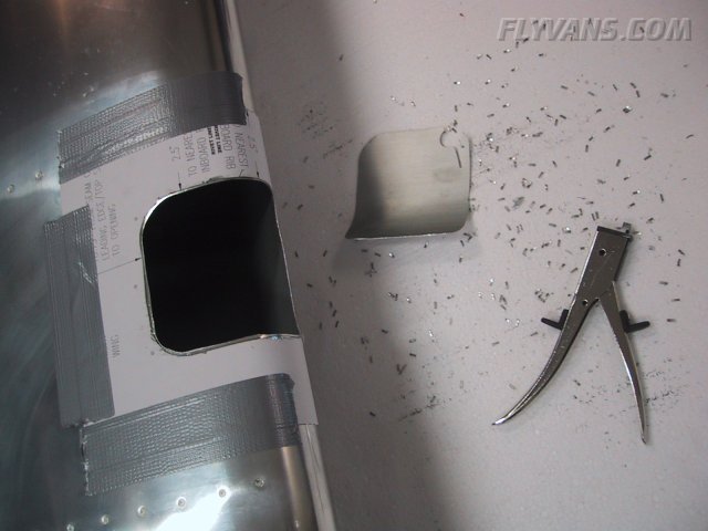
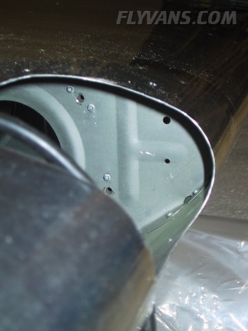
On pictures, this cutout always looks quite big. But in fact, it's rather smallish and with the QB the whole installation can be quite tricky...
Now getting the cutout from slightly undersize to exactly right, the dremel tool worked very well.
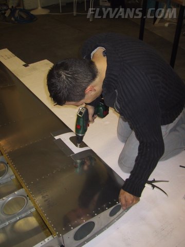
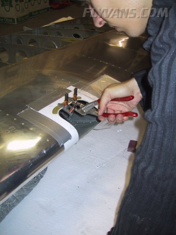
Once the cutout is done, the screw holes for the retaining strips have to be drilled to the skin.
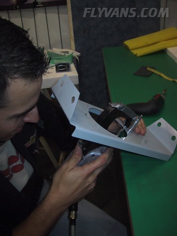
On the main bracket 2 nutplates are installed which will help attach the lamp to the bracket.
Just one picture which doesn't do justice to the work involved. First the position of the holes are marked to the ribs from a template on each side. Then the center (screw) hole is drilled to only #30. With a cleco, attach a nutplate on the cutout (wrong) side of the rib at each hole. Then drill the first wing of the nutplate #40 to the rib and cleco. Then the other wing of the nutplate. Remove the clecoes and nutplates. Final drill the center holes to screw size (3/16"). Then put the nutplates on the opposite side and cleco where possible. Pop-rivet from the cutout side of the ribs. The whole process takes place in a very confined space and again 4 hands make it happen. Complicating things is the fact, that we install the landing light in the second bay from outboard...
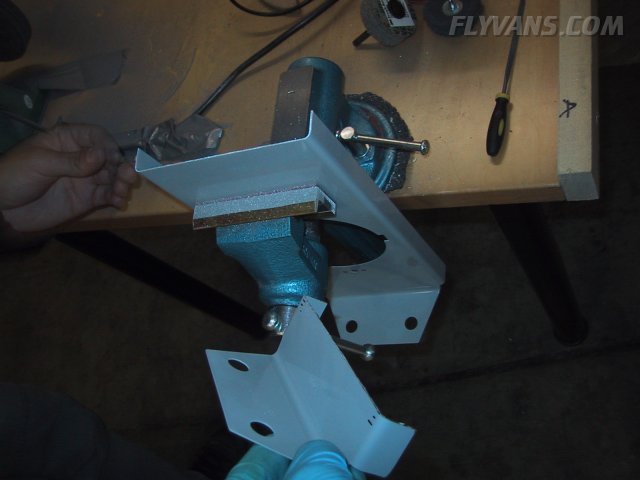
...the reasons being aesthetic and functional. As we install our AOA pressure ports in the most outboard bay, we wanted to make sure that there is no adverse effect on the boundary layer resulting from the cutout/skin-plexi overlap. Apparently this has been found not to be a problem according some posts in the vansairforce.net forums, but why take chances. Also it looks as good as if it's in the outboard bay. But there's a small problem with it, the bays are not of the same width... So we have to shorten the bracket by quite a bit...
Other than we will have to be more careful adjusting the landing light, there is no disadvantage. We already decided to mount the ballast to the inside of the outboard rib instead of to this bracket, so space is not an issue...
|
|
|||||||||||||||||||||||||
|
||||||||||||||||||||||||||
|