|
|
|

|
| |||||||||||||||||||||||||
|
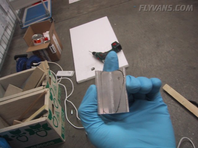
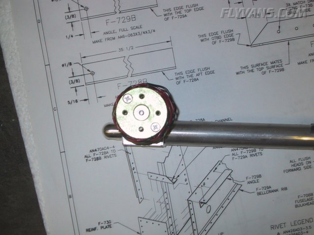
First, one of the many tiny sub-projects... Van's suggests a selfmade mount for one tiedown ring on each baggage compartment sidepanel... With the -7A we have 3 tiedowns and the selfmade nutplate as suggested by the plans (steel nut welded to a baseplate) seems heavy and too complicated. So we got some 2.5cm square aluminum profile at the hardware store of our choice and made this mount. It takes all 3 rings and will mount on the right baggage side panel. 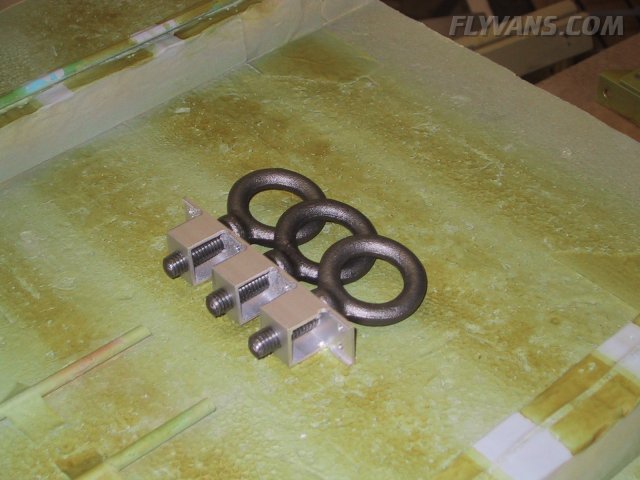
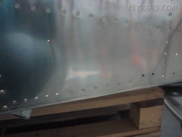
Final riveted the seatback support angles.
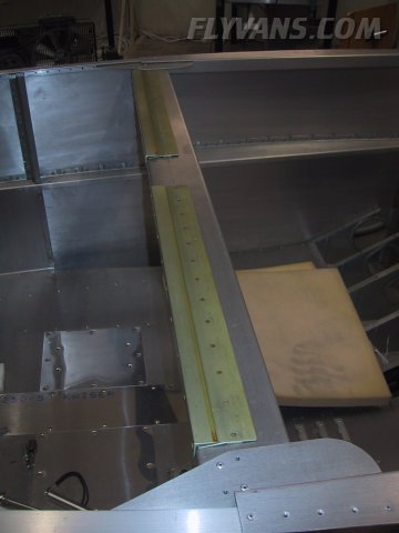
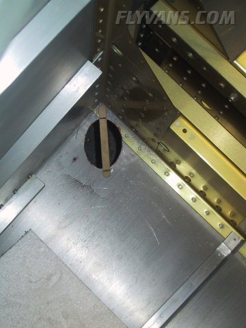
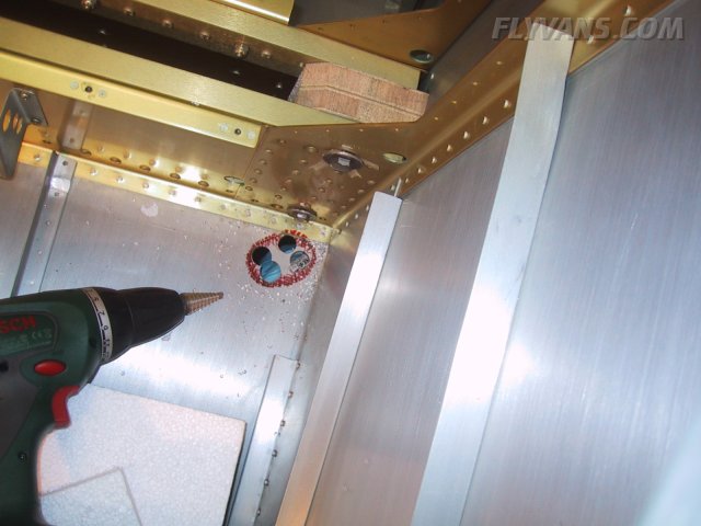
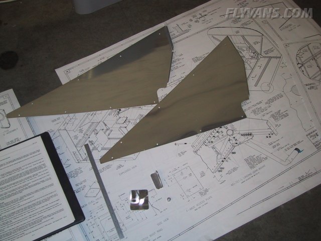
The largest share of our recent work: Making the cutout for the gear legs and fitting the weldments.
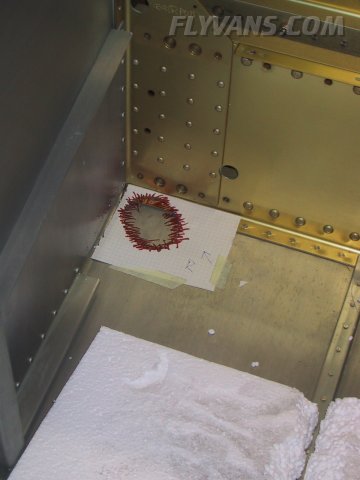
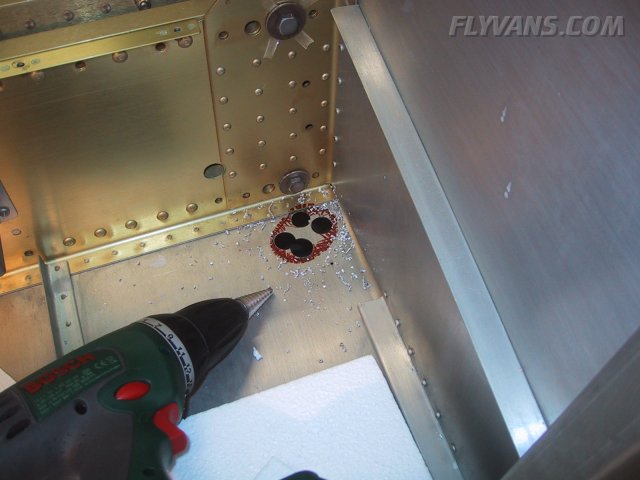
Initially drilled some large diameter holes with the unibit, then nibbled roughly from the center outwards.
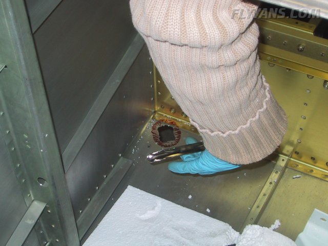
And then Mr. Dremel enlarges to final size.
Note that the bottom flange of the forward F-704 bulkhead needs to be trimmed a bit also. This has to be done with extra care, only files or sandpaper can be used. Saws or nibbling tools can cause cracks in the hardened and corrosion protected flange.
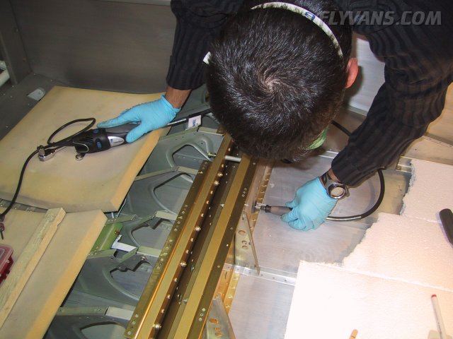
As soon as the weldment fits, it is temporarily bolted to the spar so that the outboard holes can be matchdrilled. Make sure you use a lot of Boelube and low speed, otherwise the drillbits won't last long. Also the forward 2 holes are spaced exactly one inch from center to center. This is important as the most forward hole can't be matchdrilled due to the vertical stiffener in the cabin area.
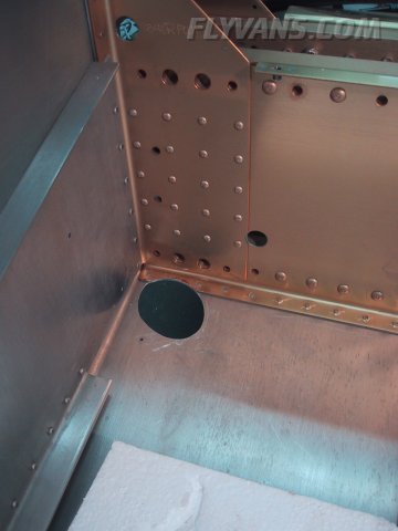
The same procedure on the left side.
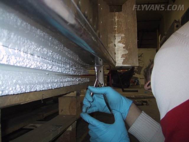
The wooden blocks that were used to attach the qb fuse to the crate now have to be removed.
Nibbling from the bottom.
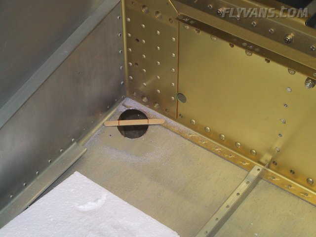
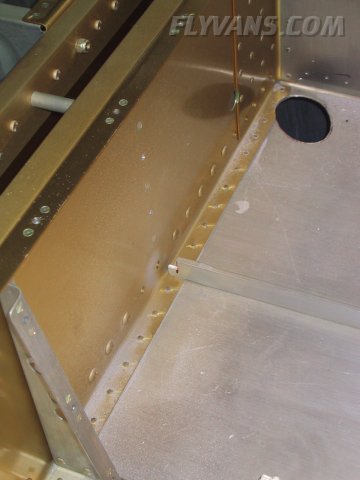
The floor stiffener has to be notched just a bit so that the weldment can be slid into place. Pictures of the weldments will follow when they are installed... But before, they yet have to be reamed to the legs.
The flexible extension for the dremel is so handy, Alex rarely operates without...
We're working on many things at the same time... There are too many dependencies to really keep track... We just go from here to there, and when one task is stuck due to missing items, we let it sit.
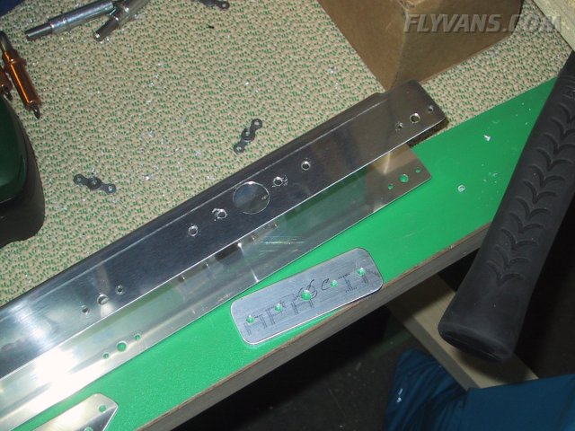
The main center bracket that will hold the electrical actuator.
And one of the angles that will turn into a bolt support.
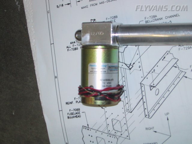
This is Van's flap actuator assembly. We hope it won't be plagued by the same issues that Van's had with a batch of motors a while ago. The brush-commutated DC motors sucked in grease to the point where they would only work intermittently and had to be taken apart and cleaned.
We also have the standard Van's flap positioning system (not shown on these pictures). It is a rather simple and mechanical construction. Maybe we should evaluate a custom positioning system via a position encoder on the (replacement?) motor.
|
|
|||||||||||||||||||||||||
|
||||||||||||||||||||||||||
|