|
|
|

|
| |||||||||||||||||||||||||
|
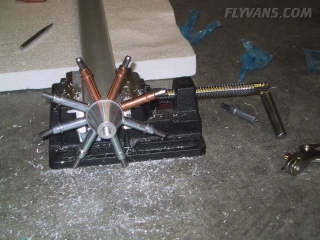
Some hardware prepared for the installation of the gear weldments. We installed them "wet" with proseal, so things have to be at hand, otherwise it's a painful and difficult process... The same goes for acetone and cleaning supplies of course. 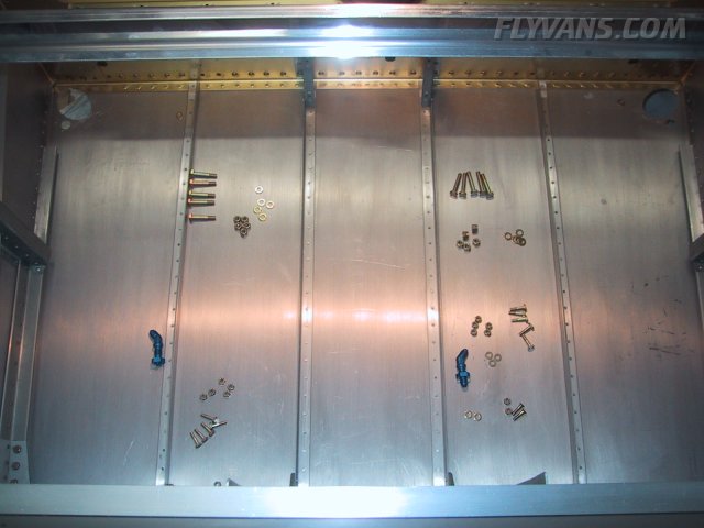
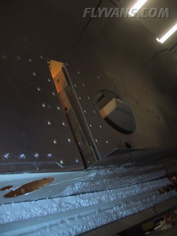
The left gear leg cutout as seen from outboard.
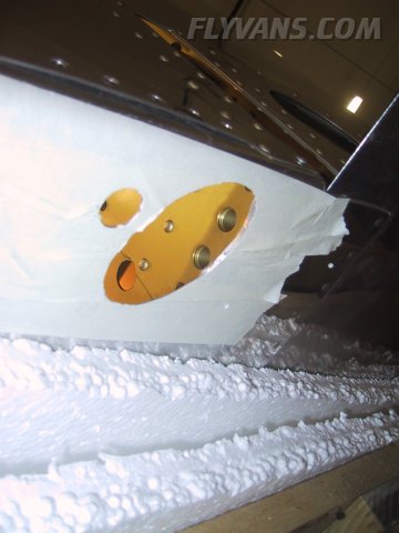
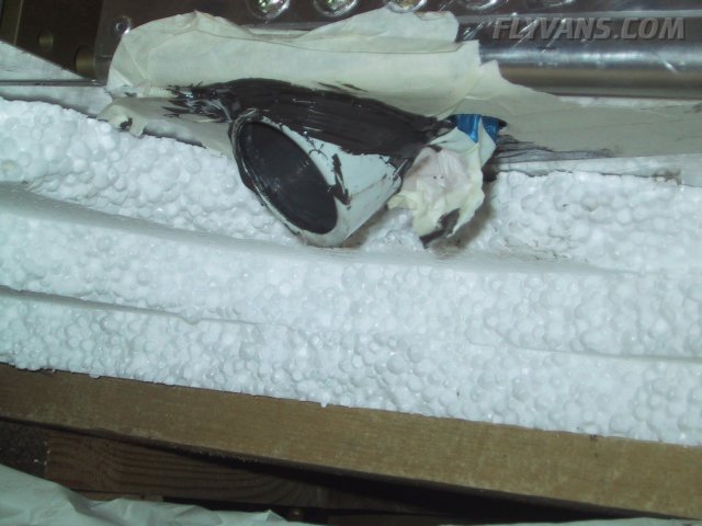
Our idea was to proseal from the inside, creating a "sandwich" between the weldment and the inside of the skin only. We haven't looked at the end result in detail yet, but it appears that it might have been better if we had masked less and would have left some space for nice beads on the outside.
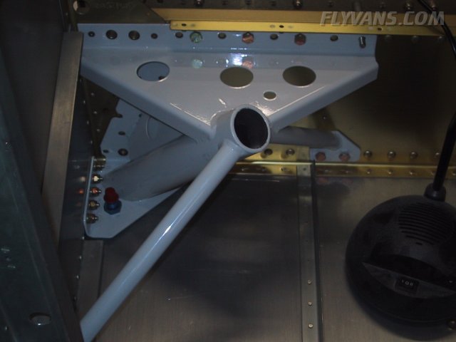
The installation from the inside. The wing attach bolts are obviously yet missing.
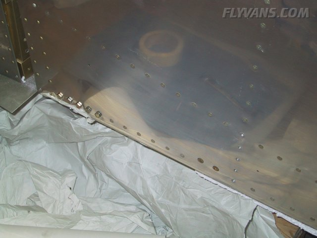
And the same installation from the outside. The bolts close to the spar will eventually be covered by the wing root fairing, while the 2 forward bolts are countersunk and flush. We also sealed them with some leftover proseal.
This picture documents the problem with the masking tape a little better. The bead now rests on the masking tape which again sticks to the skin... Less masking tape would have been better... We'll see how we go from here... Fortunately sealant is quite flexible and can also be cut away and sealed over again.
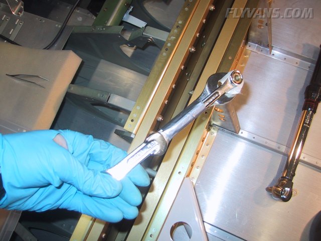
Duct tape has so many uses, it works for just about anything... Here we "extended" a wrench to be able to reach the bottom bolts. Also, some masking tape holds the nut to the wrench and by turning the bolt a few times, the nut can grip on to the bolt. Best practice of course is then to hold the bolt fixed and turn the nut only.
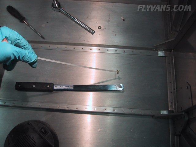
To be able to slide a washer on each bolt, we came up with a simple setup... A cable tie wrap, bent at the end to hold the washer and the chip chaser tool worked excellent. Takes a little practice, though.
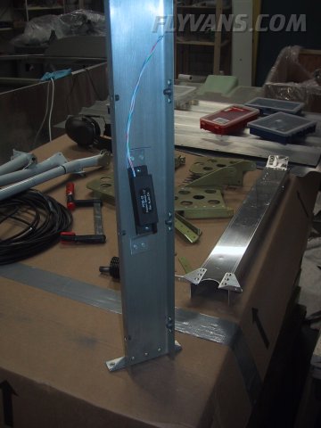
Although we haven't been able to confirm it clearly and unanimously, apparently the swiss regs require us to install a flap position indicating system, as the flaps are electrically actuated. So that requires a linear encoder to be installed. Made this bracket out of a simple strip of .032 scrap aluminum. Did some approximate trigonometric calculations to get the incidence angle for the sensor and the arm required on the flap weldment. The sensor is standard R.C.Allen. Wheter we will use a dedicated LED display or feed it to the EFIS remains to be seen.
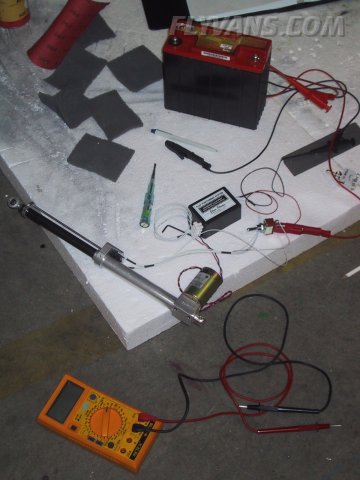
To avoid having to install the separate AOA flap microswitch, we are looking at several possibilities. One would be to use the uplimit switch of the flap positioning system. Did some measurements on when and how currents are flowing. The other option would be to use the flap position sensor shown in the picture above and derive the AOA state from there. No final decision yet.
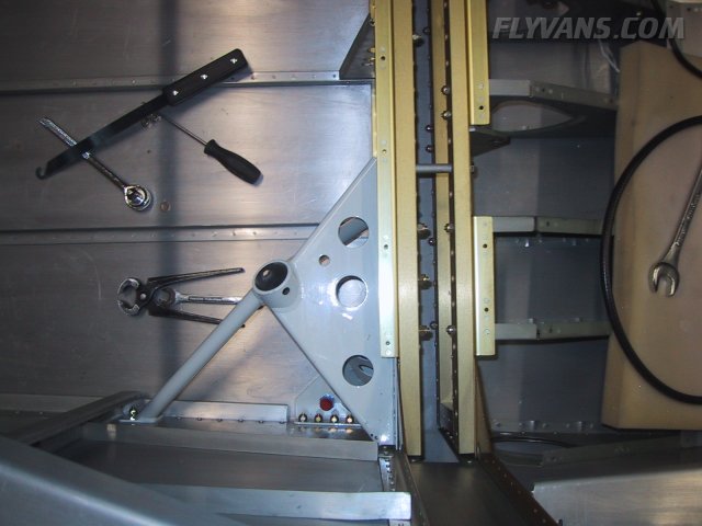
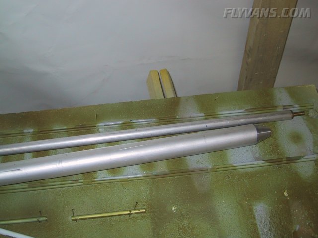
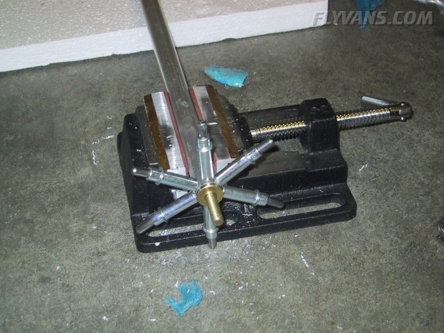
Fabricated the elevator pushrods. The smaller diameter one fits between the belcrank and the control stick weldment. The thicker pushrod is quite long and will mount between the elevator horns and the belcrank.
Drilling the endcaps.
They will attach with extra tough blind rivets, but only after the insides have been primed.
With the finish kit shipment came the crotch strap kit as well... We have read on many sites, that the brackets are easiest to install as long as there's not much else mounted yet. This proved definitely true, at least in our case. After carefully studying the instructions, it was rather a piece of cake.
Each seat floor has to be drilled to the brackets, which will receive nutplates and hold everything in position. Fortunately the seat floors came with the cutouts as well as the pilot holes already completed, otherwise this would have been the PITA part of this installation. Again we have many semi-finished pieces laying around, which means a lot of tasks will eventually be completed in quite a short time.
|
|
|||||||||||||||||||||||||
|
||||||||||||||||||||||||||
|