|
|
|

|
| |||||||||||||||||||||||||
|
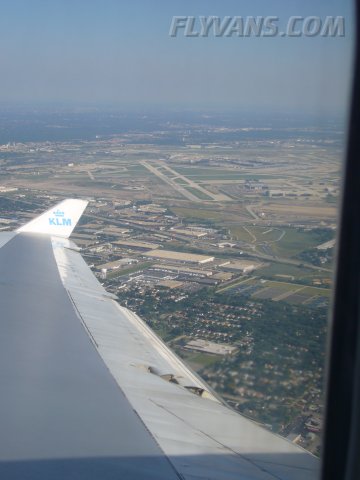
It's already a week since we returned from OSH. Found yet a couple of pictures from the trip home. B744 at the gate at ORD. 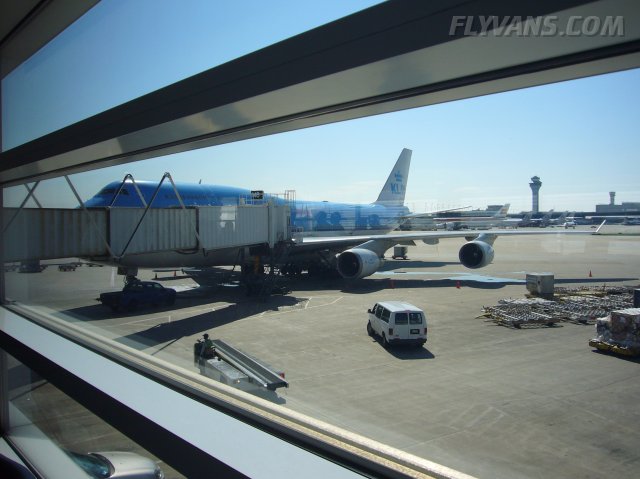
Very little taxi-time. Departure runway was practically at the end of the terminal. In a climbing crosswind with the runway in sight.
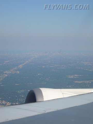
Unfortunately a bit hazy. Skyline of downtown Chicago.
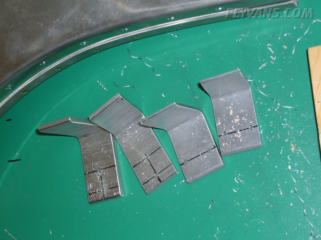
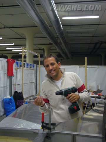
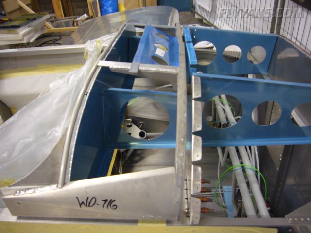
This weekend, Bernie's dad came to visit and help with 2 days of building... First and mainly we mounted the rollover bar to the fuselage. We had fabricated the brackets already but did not drill any holes up to now. We're kind of getting cautious with drilling per plans, usually locating the holes at the object will keep you from running into edge distance problems etc... How do we know? ;-)
The quickbuild fuselage is being put together no different wheter it'll end up being a tipup or slider canopy. So this deck reached back a little too far.
We trimmed it by sliding a piece of plywood beneath it and then cutting it with a dremel / cutting disk.
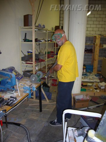
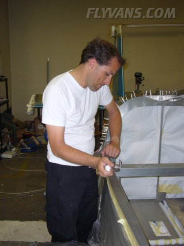
Markus edge-prepping some parts.
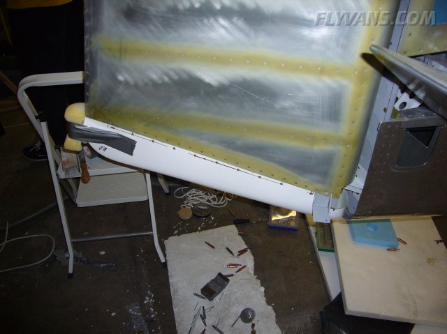
The night before I already had the rudder bottom fairing installed. Many iterations of trimming, sanding and fitting again. Unfortunately was too busy to take pictures during the process. One tip for the mounting of the taillight: A single eyelet of a piano hinge has just the right diameter to take the #4 screw from the navlight. So, cut the hole for navlight, drill the 2 holes for the screws. Then prepare 2 single piano hinge eyelets, tap a #4 thread in each. Cut the piano hinge pieces to fit in the edges of the fairing. Then temporarily mount the screws only to the piano hinge pieces on the inside of the fairing. Now i used some hot glue to fill each corner, thereby holding the eyelets in place. Make sure the main hole remains fully open. Let it cure for a bit. Now remove the screws and add the taillight, reattach the screws. Poor man's nutplate, but about the only thing that will fit since space is so limited.
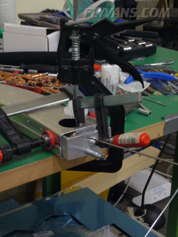
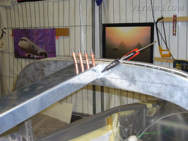
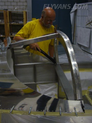
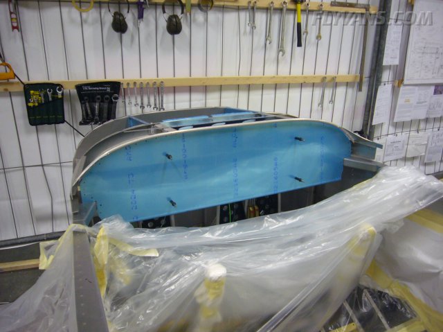
Now back to the rollbar. First the 2 brackets each are being riveted together at the correct distance.
Then, the resulting brackets are positioned and drilled to the fuselage. Enlarging to 1/4" /AN4 Bolt size. Then the brackets can be bolted on.
Then trimming the brackets on the outside to match the skin contour.
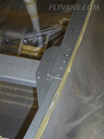
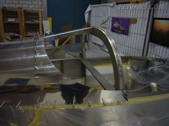
Then, the rest of the structure is built up and matchdrilled.
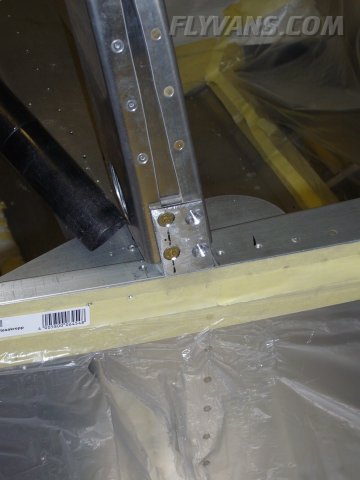
With the top skin clecoed in place.
Cleaning some of the burrs.
And finally the 4 outside bolts drilled and tapped. We made a small error here. The 2 forward outside holes need to be drilled in a very special way. Well, we simply read #8 screw, so we drilled it up to #19... Of course that's for the screw and not for a thread, there was no way to tap a #8 any longer... Also these 2 screws will pull the skin to the bracket. The easy fix was to tap a #10/32 thread, the next bigger bolt size would fit perfectly. Of course all dimples and countersinks had to be adjusted accordingly. Now we only need a couple of special order full thread AN3-bolts. Unless you're a professional RV-builder knowing all plans by heart, you won't even notice the difference ;-) That was definitely the sort of "nice" construction error to make, didn't even require a replacement part *G*
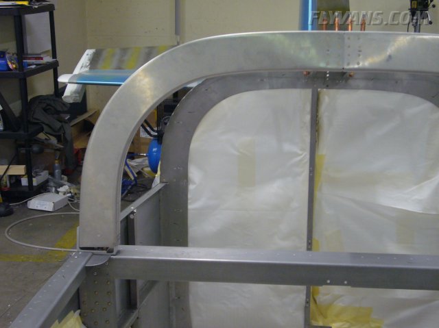
The extra care we took when we built up the rollbar a while ago paid off. Width at the base was within 0.5 mm, a perfect fit :-) Considering all the horror stories that you can read in the forums once in a while, we are really proud of our work.
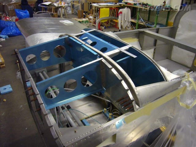
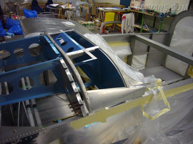
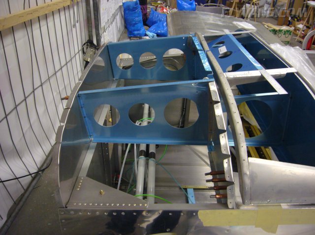
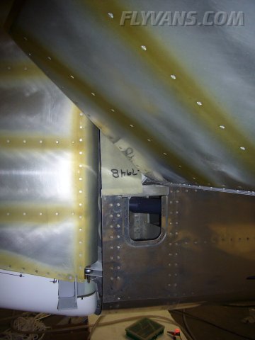
Off to the next step... Before the canopy can be built, the forward structure needs to be installed. We simply clecoed it in place just to get an idea and start planning. First of all, space behind the panel is pretty tight!, we'll even need cutouts for the longer avionics in the second bulkhead. Also, the closing canopy limits how far up instruments can be mounted in the panel. We'll also have to modify the ribs to allow for EFIS screens nicely placed in front of the pilot. This will probably mean replacing sheet with solid and heavier angle.
Also, once the top skin is going to be on, access to that area is severely limited. Must be even worse when building a slider...
This will be an ideal space for mounting the vertical power main box. Now we only have to devise some kind of platform that is easy to maintain, keeps all the cables ordered and can be lowered into the pedal area for easy maintenance.
The panel. If possible, we'd like to stick to the default panel and a custom center console. It gives a nice, clean, low aspect impression. Also the legs/knees will be much happier that way. Careful planning should make it possible.
Another view of the ribs in question.
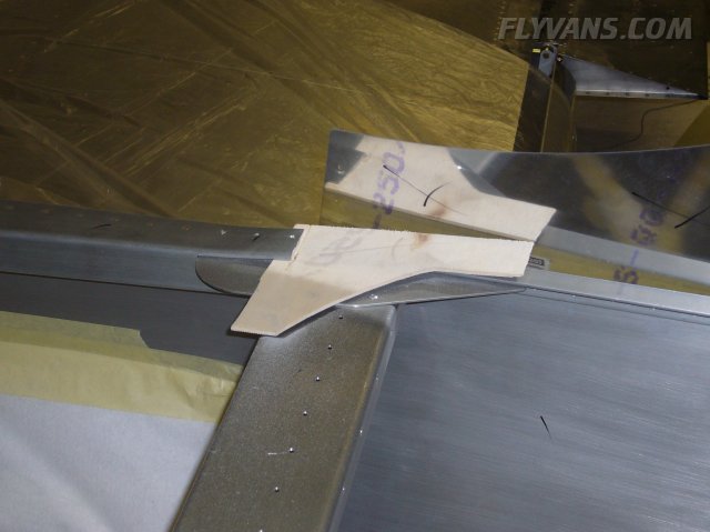
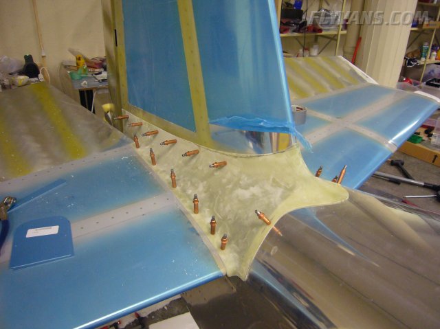
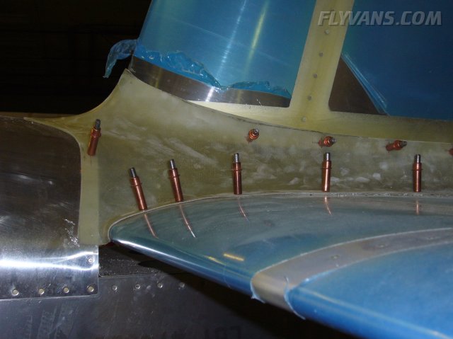
Spent some time fitting the empennage fairing... Did lots of trimming and removed quite a lot of material... For being a notorious Van's plastic part, the fitting is actually excellent! Guess we must have gotten lucky ;-)
The aft part trimmed around the elevator horns. Trimmed it just a bit too short... I've seen other guys do all metal cover plates here, might think about that.
The only area where it didn't fit perfectly, leading edge of the left horizontal stabilizer. Added an additional screw/nutplate to keep the fairing flush. Did it on the right side as well for symmetry. Up next is trimming some more near the forward part of the vertical stabilizer and fitting the bottom fairings.
|
|
|||||||||||||||||||||||||
|
||||||||||||||||||||||||||
|