|
|
|

|
| |||||||||||||||||||||||||
|
No update for a while, but we've not stopped working! It's just a lot of planning, ordering, emailing and not much visible progress.
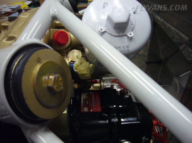
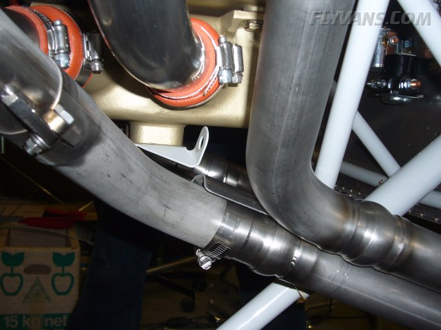
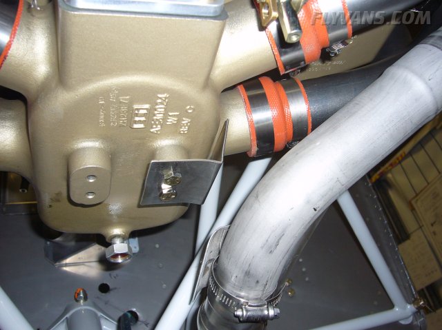
Oil cooler fitting in place. Needed to remove the oil filter for that.
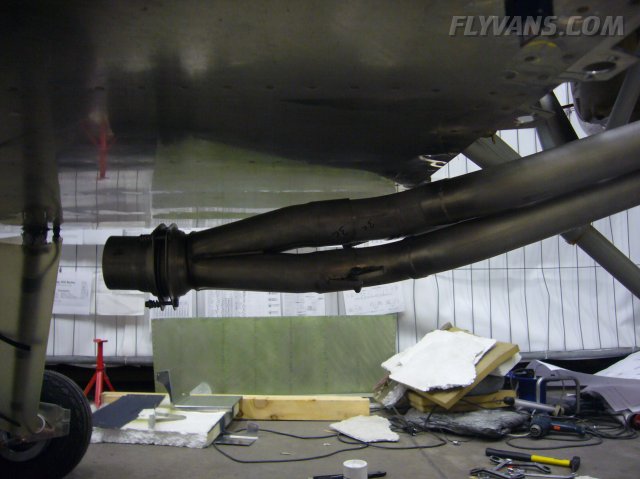
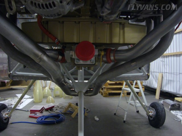
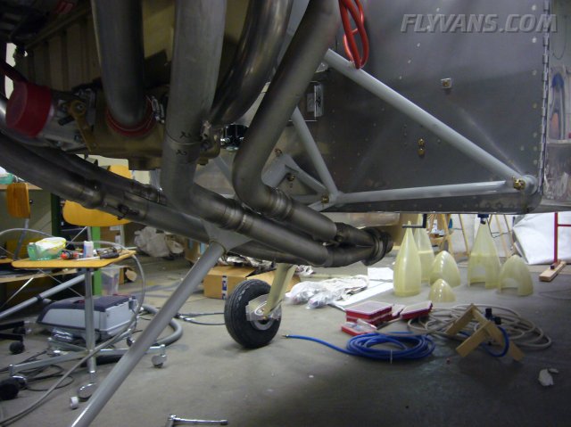
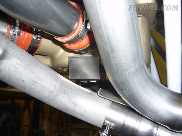
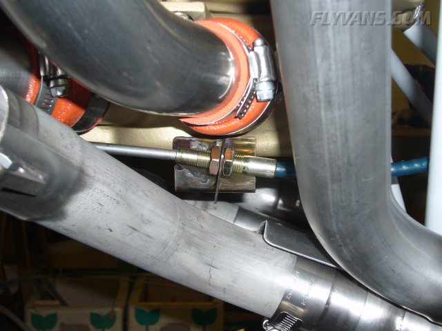
Installed the vetterman exhaust. Found loctite brand anti-seize for exhausts at a local Conrad electronics place. Everything fit perfectly and the ball joint flange is off to Liese in Germany to fit a muffler.
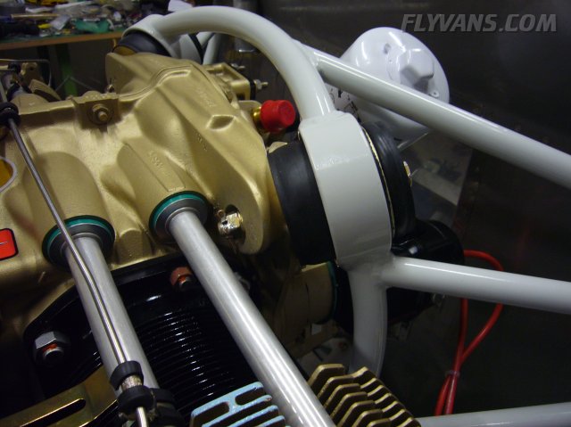
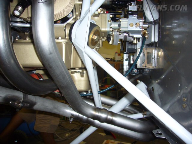
Everything on the engine is slightly angled and offset for straight and level flight. Here you can nicely see the ECI cold air induction with the magnesium oil sump and a physically separate intake plenum.
Cutting the cowl to make the exhaust fit will be another challenge.
The pipe has some 6cm spacing from the bottom of the fuselage skin.
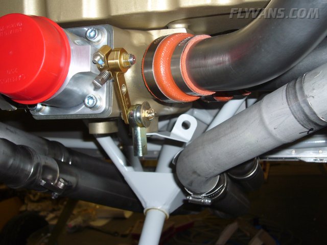
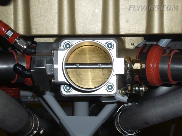
Started with the install using the standard Van's F.I. throttle and mixture brackets. But soon found out that they DO NOT work on an ECI cold air / fuel injection setup.
The Van's bracket fore/aft position doesn't give the throttle cable the right amount of travel.
But the same bolt pattern fits the intake plenum. Note that these two bolts have their heads drilled for safety wire and also use a slightly coarser thread than regular AN4 bolts!
Also had to verify that this really is approximately the idle position of the butterfly valve.
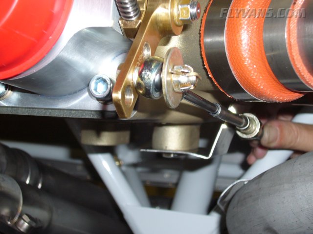
Turns out, the outermost hole on the throttle and mixture levers were designed exactly matching the travel of the control cable... BUT the control cable must have more free play to positively hit each control stop. So another email to ECI confirmed that there needed to be a third hole, slightly inboard, drilled for proper installation. Yet no documentation or right design in the first place! Frustrating... Here's the result as well as the start of a new throttle bracket.
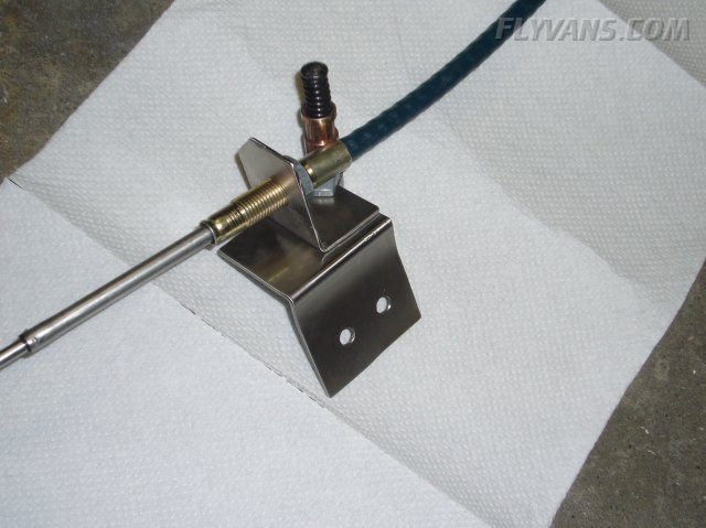
Starting a new bracket from stainless steel.
Basically two angles welded together will do.
Approximate layout. The thread of the control cable needs to be center-aligned with the two bolt holes.
Another approximate position from the side.
The control cable ends allow for up to 8° free play in each direction.
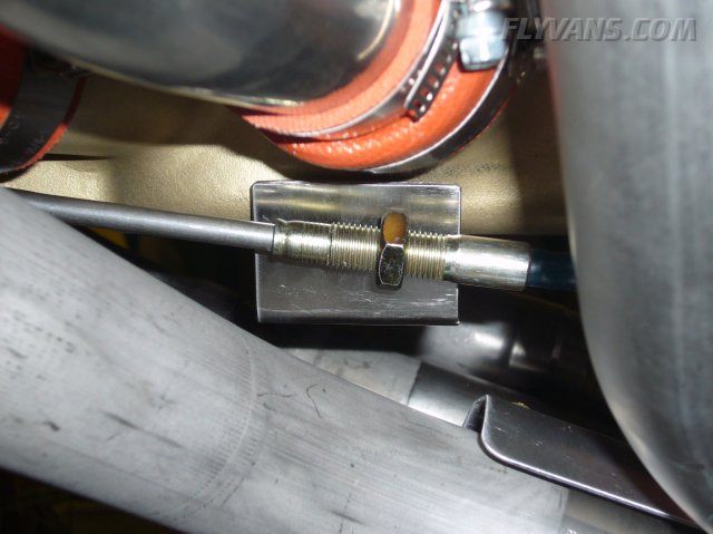
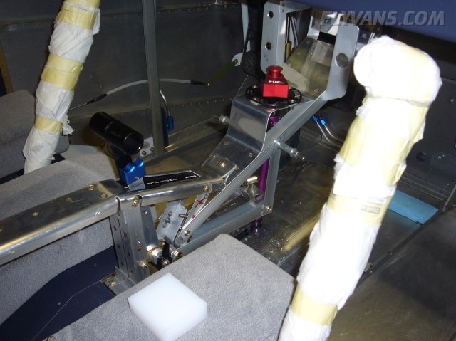
Had the bracket TIG welded. For now this should do. Depending on the input of building advisors / airplane mechanics we could redo that bracket from different material anytime if needed.
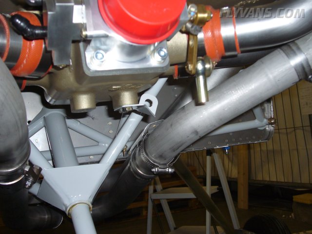
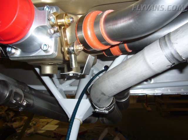
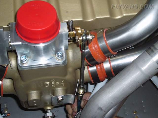
To get enough vibration isolation into the control cable, decided to route it up and through the firewall in the firewall recess instead of straight in at the bottom. When routing there, it's closer to the exhaust as well as having less freedom of motion. The cable will be firesleeved anyway later. This cable we got from another builder just for fitting purposes, it's too short for the installation.
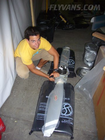
Finally, Alex came back from a half a year in the states... Unpacking and looking at our beautiful Hartzell blended airfoil propeller.
And finishing the center console with a support for the control cables here as well.
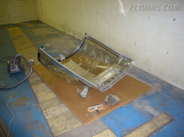
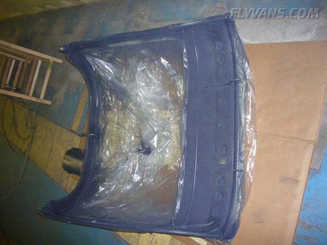
Getting ready to do some more interior painting. The canopy.
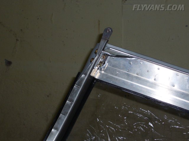
On the right side, cut some of the flange to keep the canopy from catching on the seatback while closing. We will fabricate a UHMW block that will guide the latch into the correct position later.
As with the main canopy latch, the small angle used for opening the canopy gets painted in yellow.
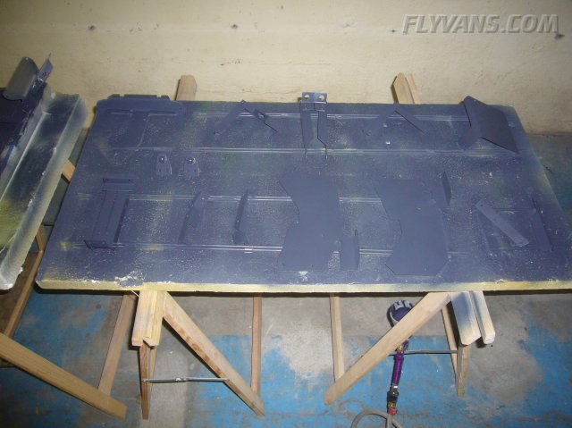
Maskin everything off and prepping for paint. Note the many small parts comprising the center covers and center console.
Lots of work again, even if it doesn't look that way.
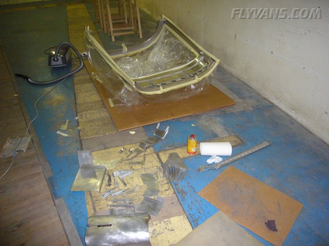
And the canopy painted. Will need a second layer as several areas are a bit thin yet.
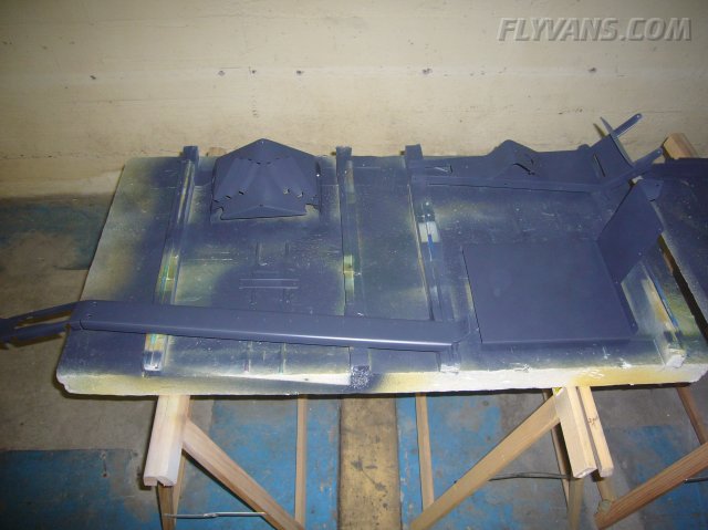
Center console pieces.
More center console.
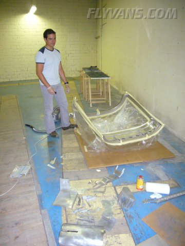
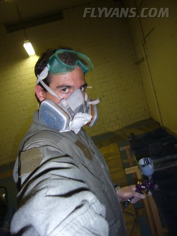
Alex our designated painter (for the inside). The outside will be done by pro's.
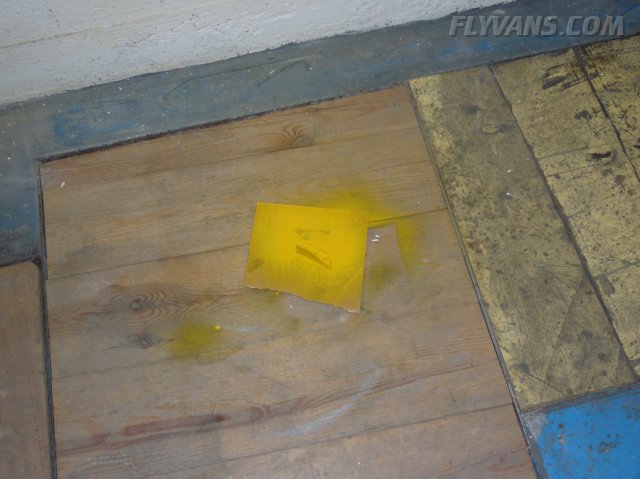
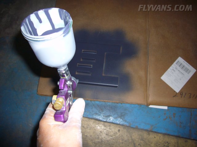
Using some extra paint to trial scrap pieces. Wheter several layers are acceptable / improve scratch resistance etc...
|
|
|||||||||||||||||||||||||
|
||||||||||||||||||||||||||
|